-Gazcut Engieering Works Ltd.")
I. Summary and features:
1. Summary:
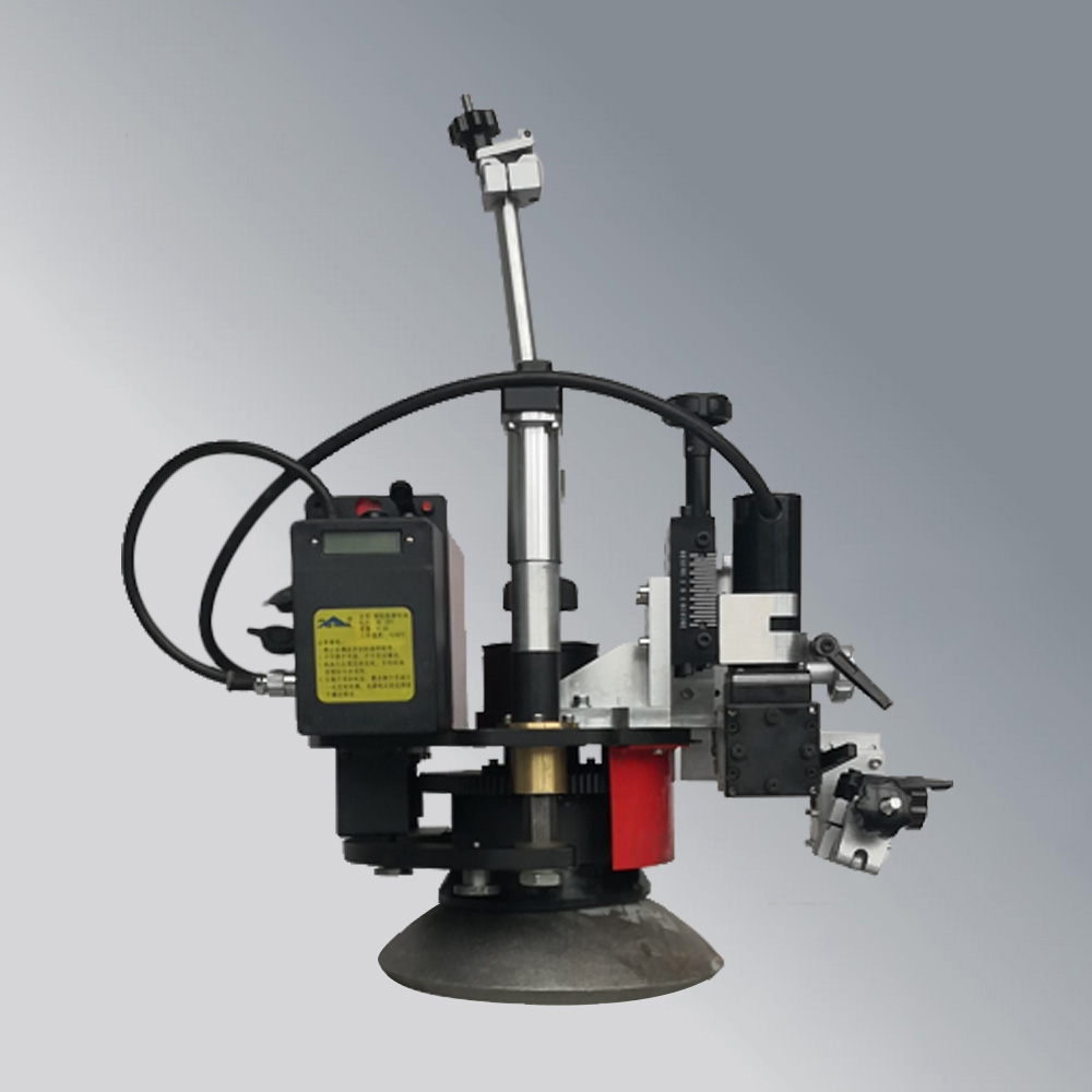
THCD-11 steel bowl welding machine is a kind of equipment used for ship welding and manufacturing, and a special welding equipment used for welding binding bowls of automobile ro-ro ships.
This equipment can meet the requirements of automatic welding of binding bowls with different diameters on automobile ro-ro ships. It is small in size, time-saving and labor-saving in moving and installing, and convenient to operate. The outside diameter of the binding bowl of the equipment is positioned, the switch magnet is adsorbed and installed, and the welding gun on the shipyard site is clamped to complete circumferential angle welding or flat butt joint. After the welding distance is set by the program, it will automatically stop, and the welding shape will be beautiful and consistent. The labor intensity of workers is greatly reduced, and the work efficiency can be increased by more than 3-4 times by one person with multiple machines.
2、Features:
⑴ This equipment can meet the requirements of circumferential welding of binding bowls with various diameters, and it is equipped with a swinging device to complete butt welding of cylindrical steel bowls.
⑵ The welding machine is small in size and light in weight, and can be operated by one person, which is suitable for the narrow space operation of the hull. It is adsorbed and installed on the top surface of the binding bowl by switching the magnetic attraction magnet, which saves time and labor in installation and movement.
⑶ The welding machine locates and installs binding bowls with different diameters by replacing positioning parts with different diameters, which has high positioning accuracy and simple operation, and reduces the requirements for operators.
⑷ The welding machine body rotates through gear transmission, which is stable and durable. The panel can be set to complete three different welding modes: 1/3, 1/2 and 1 turn.
⑸ The function button of the panel selects the diameter value of the steel bowl, and the panel will digitally display the actual welding speed during welding.
⑹ The welding machine is designed with the function of delayed start rotation. After the welding arc is stable, the rotating welding is performed, and the welding end position can be changed and set, so that the end-to-end joint of the weld is beautiful and full.
II. The applicable workpiece and shape:
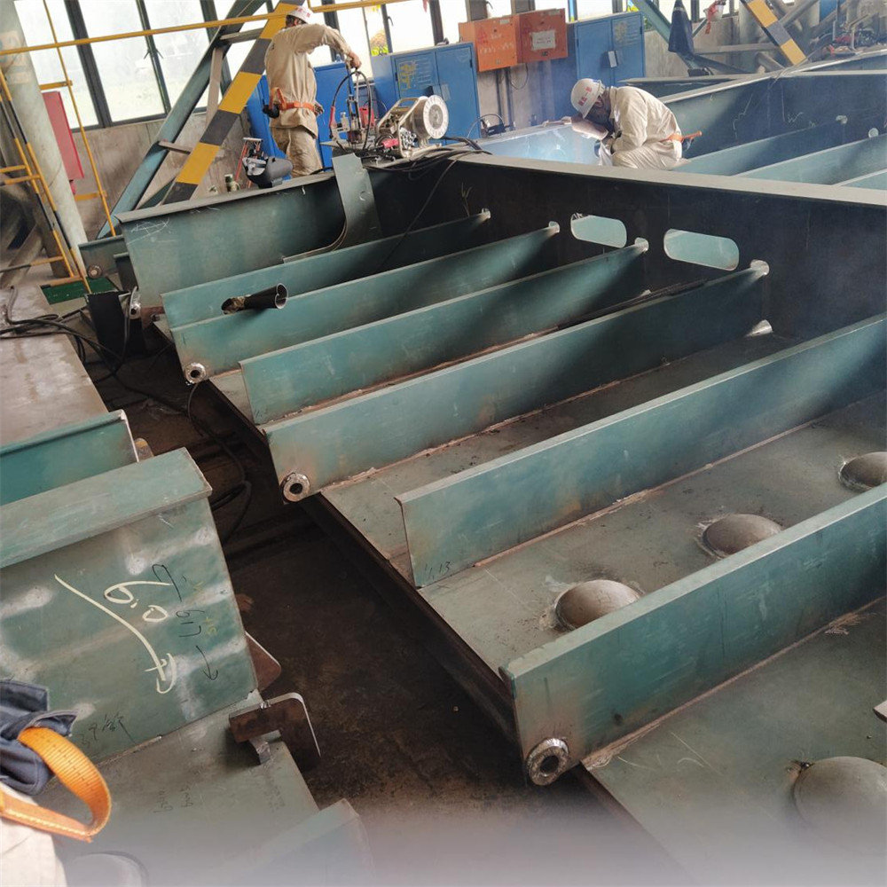
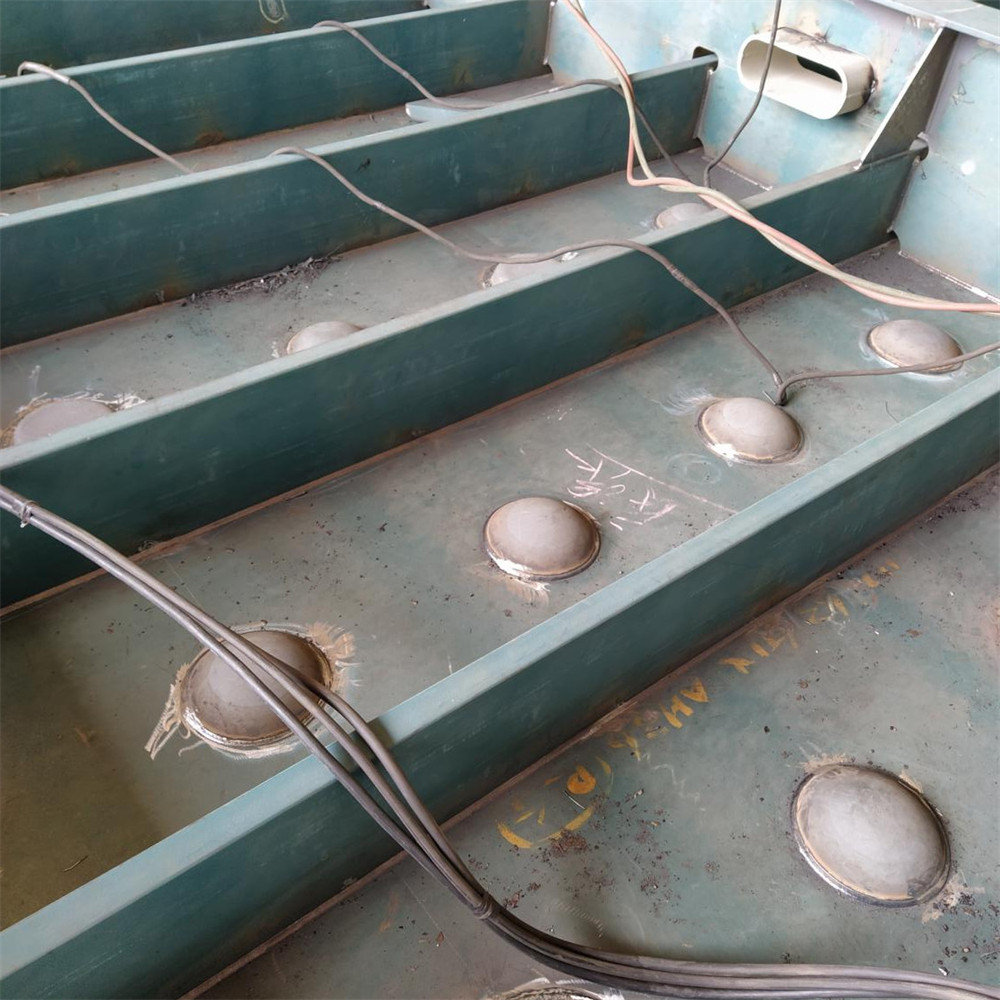
1. HCD500-1P welding machine is suitable for the external circle welding of binding bowls of automobile ro-ro ships, which can realize the corner welding of conventional binding bowls and the external circle butt joint of embedded binding bowls. It can meet the requirements of binding bowl welding with diameter of 180mm-300mm and height of 40mm-50mm.
2. The workpiece should be made of magnetic conductive material. If there is no magnetic conductivity, the magnet of the welding machine can't be adsorbed on the workpiece, which will result in the unstable operation of the trolley and the welding can't be completed. The outside diameter of binding bowl of the same specification should be uniform to facilitate the positioning and installation of welding machine.
3. Applicable to common welding wires and flux-cored wires with φ Φ1.6mm and below.
III. Specifications and technical parameters:
Item |
Naming |
technical parameter |
Electric source |
24V lithium ion battery |
Nominal voltage 24V, battery capacity 4.0Ah |
Ok, go |
type of drive |
Gear drive |
welding speed |
35~930mm/min |
|
Applicable diameter of steel bowl (optional) |
ф187mm/ф219mm/ф227mm/ф250mm |
|
Number of welding turns |
0.3 |
1/3 turn |
0.5 |
Half a turn |
|
1.0 |
1 circle |
|
Swing |
Swing angle |
0~±8° |
Swing speed |
0 ~ 40 weeks/min |
|
Left and right residence time |
0~2.5S |
|
Welding gun adjusting joint |
move horizontally |
40mm |
Vertical movement |
40mm |
|
45 degree direction |
40mm |
|
Rotate around x axis of welding gun. |
30 degrees |
|
Suction force |
25kg |
|
Machine Weight |
12.5kg |
|
Dimensions (length× width× height) |
440×360×500mm |
|
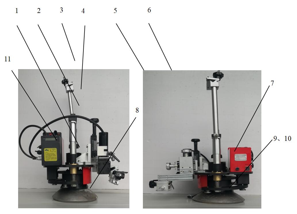
IV. Structure name
Number |
Naming |
Gongneng |
1 |
Base part |
The welding machine is attached to the binding bowl through the base part, and there are a rotating mechanism, a driving mechanism and a control box support assembly. The driving motor rotates the welding machine as a whole through the transmission mechanism to complete the welding operation. |
2 |
Positioning column |
It is used to guide the installation of welding machine and binding bowl, which is convenient for automatic rebound of positioning column after positioning without interference in welding. |
3 |
Cable fixing chuck |
Used for clamping welding torch cable. There are fastening devices; |
4 |
Handle |
Used for portable trolley, which is convenient for trolley installation and handling. |
5 |
Cross-slide adjusting assembly |
Adjust the front and rear positions of fillet welding guns within a certain range. |
6 |
Oscillator adjusting assembly |
Drive the welding gun to swing perpendicular to the weld direction, and adjust the swing angle through the electric knob to meet the needs of wide weld and molten pool agitation. |
7 |
control box |
Used for the electric operation of the trolley. See Article 5.1 Control Box for specific operation contents. |
8 |
Magnet pressing ring |
The matching magnet firmly absorbs the workpiece to prevent the welding equipment from standing unsteadily and shifting. |
9 |
locating ring |
Play that roles of guide installation and positioning column fixing, |
10 |
Positioning column |
Used for positioning and guiding the steel bowl, |
11 |
24V-4AH Lithium battery pack |
Provide power to the trolley, and reduce its dependence on external power. |
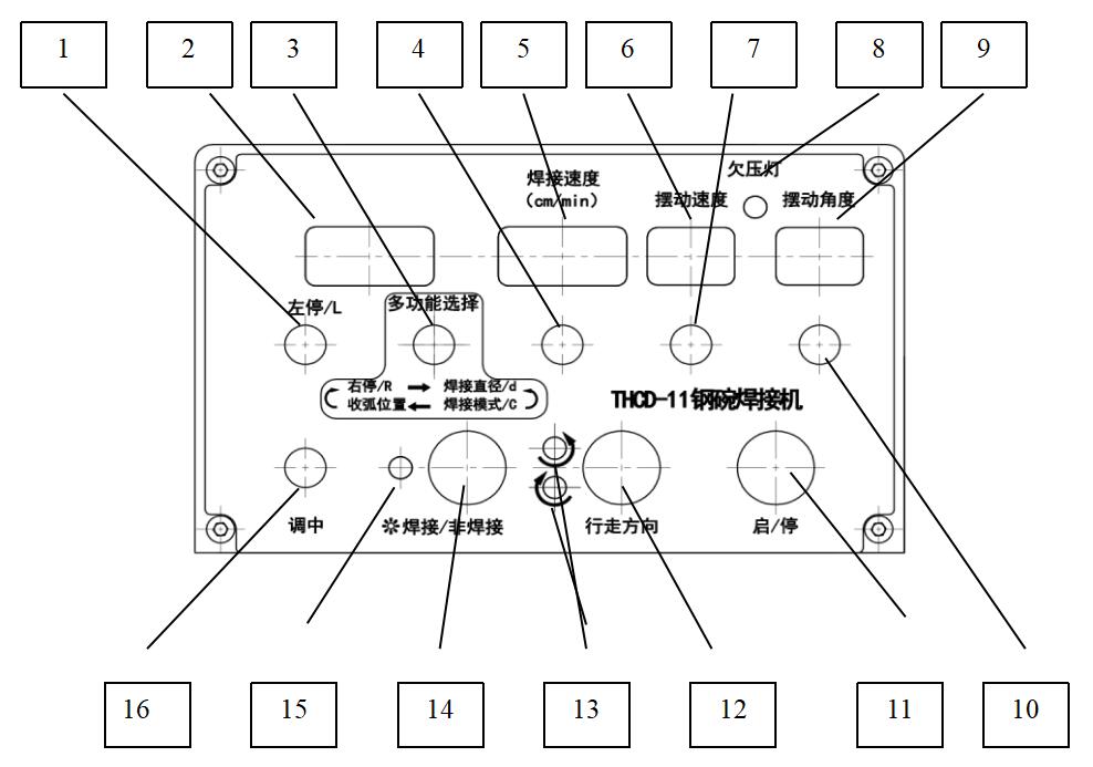
V. Control box function key name function
Number |
Naming |
Function |
1 |
Swing left stop time Adjusting potentiometer |
Rotate the potentiometer shaft to adjust the swing left stop time. The clockwise parameter increases and the counterclockwise parameter decreases. |
2 |
Multifunctional selection Display nixie tube |
The format is X Y.Y To display the mark X, you can press the rotary shaft of the multifunctional selective adjustment potentiometer to switch circularly between R-D-C-. R represents the dwell time of the right extreme position of the swinger; D represents the diameter of the steel bowl; C indicates welding mode; -Indicates fine adjustment of arc closing position. Rotate the left stop potentiometer to switch the meeting L and display the left stop time. |
3 |
Multifunctional selection Adjusting potentiometer |
The rotary shaft of potentiometer has the function of pressing, which is used to display parameter switching (see the previous item for details); Rotate the potentiometer shaft to adjust the time parameter corresponding to the displayed parameter mark. The clockwise parameter increases and the counterclockwise parameter decreases. |
4 |
welding speed Adjusting potentiometer |
Rotate the potentiometer shaft to adjust the welding speed value. The clockwise value increases and the counterclockwise value decreases. |
5 |
welding speed Display nixie tube |
The format is XXX, which is used to display the actual welding speed of the welding machine (related to the diameter of the selected steel bowl). |
6 |
Swing speed Display nixie tube |
The display format is XX, which is used for proportional display of swing speed. |
7 |
Swing speed Adjusting potentiometer |
Rotate the potentiometer shaft to adjust the swing speed value, which increases clockwise and decreases counterclockwise. |
8 |
Undervoltage indicator lamp |
It is used to indicate the battery power. When the undervoltage indicator lights up, it indicates that the battery power is insufficient and needs to be charged. |
9 |
Swing angle Display nixie tube |
The format is XX, which is used to display the swing angle proportionally. |
10 |
Swing angle Adjusting potentiometer |
Rotate the potentiometer shaft to adjust the swing angle, which increases clockwise and decreases counterclockwise. |
11 |
Start-stop switch |
Start-stop status multiplexing button, press to switch the start-stop status; |
12 |
Running direction switch |
Used to switch the running direction of the trolley. Every time the trolley is pressed, the running direction of the trolley is switched between clockwise and counterclockwise. |
13 |
Walking direction indicator |
Indicates the rotation direction of the trolley. |
14 |
Welding/non-welding control switch |
Used to control welding/non-welding status. |
15 |
Welding indicator lamp |
The indicator light is on, indicating the welding status; Otherwise, it is in a non-welded state. |
16 |
Medium potentiometer |
Used to adjust the position of the swing center of the swinger, clockwise to the right and counterclockwise to the left. |
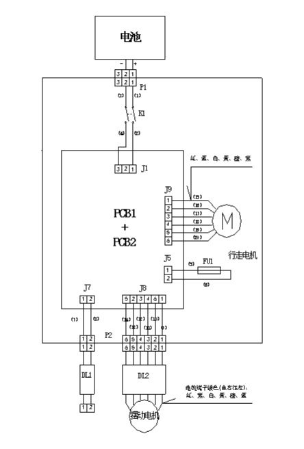
VI. Electrical principle